Wednesday 2 March 2011

Adding texture to the tire


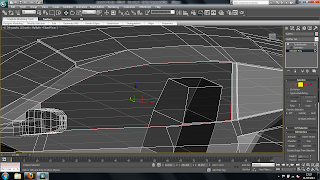
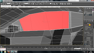
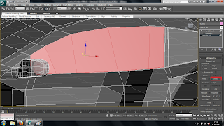
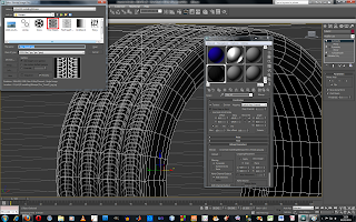
To add tire tread to the outside of the tire I first detched the outer surface of the tire as a seperate element so that only this sruface would be affected by the material. I then opened the material editor tool bar used the bump tool under maps and clicked none to add in the bitmap i had found from the internet of a tires tread.
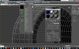
This brings up another tool screen as shown in the picture above. By choosing the bitmap button and clicking ok it then brings up a window with bitmaps that can be used. I chose the correct bitmap and clicked ok.
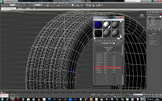
At first the bitmap will not fit on the tire correctly until you tick the real world scale button and use the hieght and width to size the image until it fits correctly to the object. This is shown in the picture below.
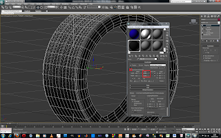
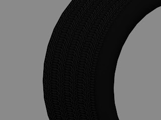
Once this has been doon the size of the bump can be changed by changing the number in the maps menu.
Modelling the Gun


Reference:
Walther PPK pistol fitted with silencer [Image online] Available at: [Accessed 01 Feb 2011]


To model the gun I first drew a long box and then shaped it using the vetex selection button. I also used the extrusion, bridge, cut and connect tools to shape the body of the gun until i was happy that it look like the picture I had found from the internet.

I modelled the gun in the same way as the cars by only modelling half of it and then using the symmetry tool to make both sides of the gun exactly the same.

Once I was happy wit the shape of the body of the gun i moved onto creating the silencer for the gun. To do this I creating a cylinder as a seperate object and then used the extrusion tool to add detail to the object. I then attached this object to the main body of the gun and used the turbosmooth tool to soften the edges of the gun.

Tuesday 1 March 2011


To finish the cars I used the Turbosmooth tool found the in the modify drop down box. As I only modeled half of the car I also used the symmetry tool to make sure the car was completely symmetrical. To get the symmetry tool to work properly I played around with axis using the extra tool bar and positioned the mirror image in the right position.

Reference:
Freetutorials4you, 2010. 3DS Max tutorial: Modeling car 1 - 64. [video online] Available at: [Assessed 03 Feb 2011]

Driver


To finish the car off i made a simple silhouette of the insdie of the car as well as the driver and the sterring wheel. I created the driver by using the extrude and bridge tools and then shaping him until it looked more realistic.

Creatin the Wheels


To create the wheels I first drew a tire using the tube tool under standard primitives and moved it into place. I then selected the entire outer edge to the tire by using the edge tool and the loop tool. To add more geometry i used the chamfer tool, this created a better curvered edge to the tire. I then selected the middle edge on the fron face of the tire and again used the loop tool to select the whole ring. With this selected i dragged this ring out slightly to create a slight buldge in the tire to make it look more realistic.

To create the wheel itself I then drew another tube, as a seperate object, just inside the tire, however this time I changed the amount of segments there were on the cap face to 60. Once I had shaped this and put it in the right place i then drew a cylinder in the centre of the ring and made sure that this had 30 segments on the cap face and then attaching it to the first object to make them one object. By making the outer ciircle have 60 faces and the inner circle have 30 faces i could accurately place the 5 spindles the same space apart. To do this I simply selected 3 polygons on the inside tube and 3 opposite polygons on the outside tube and then bridged them together creating one og the spindles. I then left a gap of 3 polygons on the inside tube and 9 polygons on the outside tube and repeated the process. I repeated this again 3 more times and the wheel was created. Using the inset tool and extrusion tool I add in the dimensions of the centre of the wheel.

To finish off the wheel i added a brake disc. I did this simply by drawing a cylinder just inside the wheel and adding a box to it to create the calipar.

Wing mirror


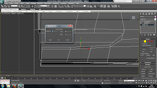
To create the wing mirrors of the car i set the view looking straight onto the car and draw a box, as a seperate object, that was slightly bigger than the 2D picture of the wing mirror. I than moved the box into the right postion and converted the box into an editable poly. Using the vertex of the box i shaped it into the shape of the mirror according to the drawings from the top, front and side. Once I was happy with the shape of the mirror I extruded some of the polygons facing the car into the part of the model where the wing mirror should be attached. To extrude these polygons i used the extrude tool which opens up another tool bar in which you can increase and decrease the size of the extrusion and by clicking apply create more than one extrusion to give you more polygons. Making sure that the extrusion was intersecting the side panel of the model I shaped the extrusion to meet the car more smoothly. With the shape of the wing mirror completed I then selected the car model itself and went into the editable poly tool bar and used the attach tool to make the car and the wing mirror one object. I repeated this method to create the grill and other similar features of the car.

Creating the lights and windows


Once the holes have been made in the body of the model for the lights and windows use the border selection tool to select the edges of these holes. With the border of one of the windows selected hold shift and drag the selection towards the inside of the model, this will create a thickness to the body. The next tool I used was the bridge tool. The bridge tool connects 2 opposite polygons with another polygon. To do this for the window I selected 3 edges at the top and bottom of the window and clicked the bridge tool. An extra tool bar is available to add in extra geometry and polygons.

However doing this will only cover up part of the hole, therefore to do the rest I again used the boreder selection tool to select the small hole that was left and used the cap tool to completly cover over the hole and create the window. The reason I didnt just use the cap tool to create the window straight away is because this tool only adds in one polygon whereas using the bridge tool edges and extra polygons are created so that the window can be shaped more easily.

As the window will be made from a different material aas the rest of the car the window itself needs to be seperated from the car model. To do this I used the polygon selection tool to select all the polygons that make up the window as shown in the picture above. I then clikced on the detach tool to seperate it from the rest of the body. Rather than making it a seperate object completely I turned it into a seperate element in the already existing model. By using the element selection tool I can then select the windwo individually and make it into a different material to that of the body. I repeated this method for the rest of the windows as well as the lights.

Monday 28 February 2011


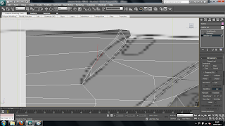
Once the basic model of the car as been made detials to the model can be introduced. To do this I used the connect and cut tool which add in lines and polygons to the model to make it more detialed and smooth. The connect tool adds a centre dividing the polygon into 2 peices creating 2 polygons. When using the connect tool you can bring up an extra tool bar to control where the line will go and also add more than more line in a a time. By doing this sharp edges on the model can be produced as the smooth toll that will be used will curve everything, however by adding more lines closer to each other in the right places will sharpen them. This is shown in the pigture above.

Another tool i used to add in detials and shapes that needed cutting out such as the lights and the front grills of the car was the cut tool. This tool also adds in extra lines however there is more freedom in using them as the line doesnt have to be straight like in the connect tool. However the line you draw in must finsih at an already existing edge otherwise the programme will finish it for you and it might not be in the right place. Once these lines are put in you can select them by using the edge selector and using the loop or ring tool which will select many edges in relation to the first one selected. This allows you to move parts, such as the groves in the bonet, to produce flowing curves on a whole surface. Using both these tools i created the holes for the lights, windows, grills, grove in the bonet and boot and space for the exhausts.

Modeling Continued


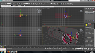
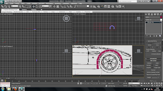
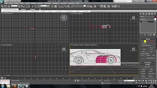
Once each of the views of the car have been imported into 3DS max you can start modeling the car. First draw a tube from the standard primitives tool bar the same saze as the wheel arch of the front and rear of the car. The heigth of the tube doesnt matter as the tube needs to be deleted down to a 2D drawing.

To do this convert the drawing to an editable poly by right clicking the selected drawing and chosing convert to editable poly. Select all the vertex of the drawing apart from the front face and delete them to leave you with a 2D ring drawing. Then delete the bottom polygons that are not needed and move the vertex to meet the bottom of the wheel arches.

Once this is done you can start shaping the car by selecting edges and holding shift to drag out more polgons. The using the vertex and the edges you car slowly build up the shape of the car. You only have to draw half of the car as the symmetry tool can be used to produce the other side.

Mdoeling Aston Martin DB9


To start modeling the Aston Martin a 2D line drawing of the car must be found to base the model of the car on. I found this one through searching on google images. Once i found this i had to split the picture into the seperate views of the car to make it eeasier to import into 3DS Max. To do this i opened the image in Photoshop and croped the picture down to each of the seperate views and saved each one.

Then, once this is done, draw a plane in 3Ds Max draw a plane from the standard primitives tool bar in the front view port. Go into the modify tool bar and set the height and width of the plane to 10% the size of the images that have been cropped. This will provide an accurate side front drawing of the car that will be to scale. Once this is done the image can be placed onto the plane through the material editor and adding the image as a bitmap and dragging it onto the plane.

James Bond scene


The scene i've chosen is the car chase on the ice in the film Die Another Day set on a frozen land with ice mountians in the background. The scene has 2 cars, an Aston Martin DB9 and a Jaguar XK, chasing each other with hidden guns and rockets on each one. I chose this scene as it is one of the most memorable James Bond films i've seen as it was released around 10 years ago. Also i'm into cars and would like to try and model a car on 3DS Max. The Three things i will be modeling for the first half of the assignment will be the 2 cars, the Jaguar XK and the Aston Martin DB9, and a pistol.

References:
Walther PPK pistol fitted with silencer [Image online] Available at: [Accessed 01 Feb 2011]

Die Another Day - US Advance Poster [Image online] Available at: [Accessed 01 Feb 2011]

Die Another Day - Gun Barrel [Image online] Available at: [Accessed 01 Feb 2011]

Die Another Day -Aston Martin V12 Vanquish [Image online] Available at: [Accessed 01 Feb 2011]

Die Another Day -Aston Martin V12 Vanquish and Jaguar XKR [Image online] Available at: [Accessed 01 Feb 2011]

Die Another Day - Jaguar XKR [Image online] Available at: [Accessed 01 Feb 2011]

Like many Bond cars, the Aston Martin V12 Vanquish from Die Another Day had a few secret weapons, 2008 [Image online] Available at: [Accessed 01 Feb 2011]

James Bond Aston Vanquish Chase Sequence [Image online] Available at: [Accessed 01 Feb 2011]

Airstrike92, 2009. James Bond - Die Another Day Car Chase [Video online] Available at: [Accessed 01 Feb 2011]

Monday 21 February 2011

Cheese Board


Using all the tools ive learnt so far i Created this table setting made up of a fruit bowl, cheese, a wine bottle and a wine glass or goblet.

Boolean


The boolean tool is used to cut shapes out of other shapes, like i have done to create the fireplace above. Firstly a 3D object needs to be drawn, for the fireplace a simple box needs to be created using the box tool. Once this has been done another 3D shape needs to be drawn, for the fire place a cone shape can be drawn using the cone tool under the simple shapes tool bar. At first the objects probably wont be intersecting. So simple move the cone shape into the box with the size of the cone sticking out abit. Then chose the boolean tool under the create, compound objects panel. Simply select the subtraction A - B tool and then select which object is A and which is B and the programme will do all the work. Using this tool however will dramatically increase the file size of the object and increase the rending time.

Lathe

The Lathe tool is used to create models of bottles and pots. To create an object with the Lathe tool first a cross section of half of the pot must be drawn, as shown in the image below. Once the cross section is complete go into the object hirearchy in the right hand tab and select the Affect Pivot only tool. With this selected you will be able to move the point at which the cross section drawing will rotate around.

With the cross section drawn and the pivot point moved into place select the lathe tool which is found under the modify section and from the modify list select the lathe tool. The model may not look right straigth away so just select the a different axis until the the model looks as it should.

Lofting


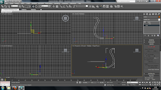
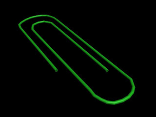
To produce an object using the loft tool first a 2D line drawing of the shape is drawn using the line tool which is found in the create, shapes section on the right hand side tool bar. Another drawing of the cross section of the object then has to be drawn. In the case of the paper clip just a 2D circle is all that is needed for the cross section drawing. Once this has been done drag the circle and move it so that it is in line with the line drawing of the paper clip. Then go into the compound objects, in the drop down bar under the create section. Select the line drawing of the paper clip and then select the loft tool in the right hand tool bar. Another tool bar will pop up in the right hand tool bar select the shape button and click on the paper clip. This turns the 2 2D drawings into one 3D model of a paper clip.

Thursday 27 January 2011


To create the apple and the orange spheres were drawn, however as oranges and apples srent a perfect circle shpe the objects needed to be modified. To do this the object has to be converted into a poly done by right clicking the object and selecting the convert to poly tool. This will add vertex to the object that can be moved individually and change the shape of the object to match the more natural shape of apples and oranges. To create the Banana first draw a prism with about 5 sides using the gengon tool and then turn the object into an editable poly. Drag the top and the bottom of the shape out to make it ends pointy. Then in the modify list select the bend tool to create the bend in the banana. Once this is done use the turbo smooth tool in the modify list to create the smooth shape to the banana. The Bowl was created using the lathe tool.